Product

Osteoxin Extraction Tank

Overview

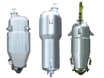
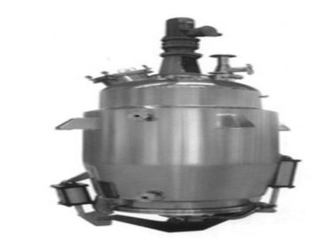
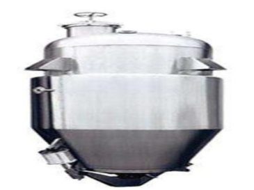
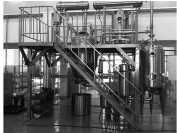
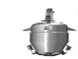
The bone extracting tank is used to extract essence and umami substances from pig bones, cow bones, sheep bones, chicken bones, fish bones, or meat, such as amino acids, bone peptides, bone oil, etc. It essentially extracts umami essence from fresh bones, originating in Japan in the 1970s and later introduced to other regions. Bone extract meets the modern demand for natural, delicious, authentic, and nutritious ingredients.

Extraction Process Steps

 Preparatory Cleaning and Sterilization
  • Clean the tank interior thoroughly and sterilize it to ensure no contamination.
2. Feeding Materials
  • Load bones or bone fragments into the tank through the upper feeding port.
  • Open the water inlet valve and add 5 to 8 times the volume of water (or organic solvent) relative to the bones, as specified by the preparation process.
  • Leave a certain space in the tank after adding bones and water to prevent overflow caused by foam generation during heating.
3. Heating and Extraction
  • Turn on the steam for the tank jacket. For rapid heating, simultaneously open the direct steam valve inside the tank to bring the solution to a boil quickly.
  • After the solution in the tank boils, the steam (carrying oil components with lower boiling points) rises to the condenser, then flows through the cooler to the oil-water separator.
  • Separate and collect the oil in the separator based on the principle of different oil-water specific gravities. Once most oil is collected, return the solvent from the separator to the tank to maintain the solution volume.
4. First Extraction Discharge
  • After the first extraction, close the steam valve.
  • Open the liquid discharge valve, filter the extracted liquid, and transfer it to the storage tank.
  • (Note: Most bone extracting tanks are equipped with a stirring system to ensure thorough extraction.)
5. Subsequent Extractions
  • Second Extraction: Add fresh solution and extract for about 1.5 hours using the same method as the first time, then combine the extract with the first batch.
  • Third Extraction: Add solution again and extract for 40 minutes to 1 hour, then combine all three batches of extract.
6. Residue Discharge and Cleaning
  • After extraction, open the slag discharge door to remove bone residues once the essence substances are fully dissolved.
  • Perform in-place cleaning (CIP) by opening the cleaning valve, then close the discharge door and prepare for the next batch.

Precautions

  1. Operation Pressure & Temperature Control
    • Operate strictly according to the working pressure and temperature specified on the product nameplate to avoid hazards.
  2. Maintenance & Lubrication
    • Adhere to the regulations on cooling, oil injection, and other requirements in the product manual to ensure proper equipment maintenance.
  3. Valve Operation
    • When using any valve, slowly rotate the valve stem (needle) to press the sealing surface for tightness. Avoid excessive force when closing to prevent damage to the sealing surface.
  4. Electrical Control & Safety
    • Electrical control instruments must be operated by designated personnel, and overload protection facilities should be set up as specified.

Installation and Use

  1. Installation Location
    • Install the extracting tank on a sturdy, level workbench. The workbench height should be determined based on operational needs. Leave a space of at least 200 cm around the equipment and allocate space for material discharge to facilitate installation and future maintenance.
  2. Verticality Requirement
    • Ensure the transmission shaft is perpendicular to the horizontal plane during installation. The non-verticality (tilt) must not exceed 1/1000 of the equipment’s total height.
  3. Accessory Configuration
    • Self-provided parts and safety valves on the process pipes of the equipment must comply with the specifications of the extracting tank.
  4. Leakage Test
    • After installation, check that all connection components and transmission parts are firm. Conduct an airtight test on connecting pipes, nozzles, seals, and the entire machine to ensure no bubbles, leaks, drips, or seepage occur.
  5. Pre-Startup Checks
    • Before starting, inject mechanical oil into the reducer. Remove the motor protective cover and manually rotate the fan blade to check for jams. Ensure the stirring paddle does not scrape the tank wall. Clean the kettle interior before starting. Run the machine empty for 30 minutes; if no abnormal noise or vibration occurs, it can be put into formal production. Additionally, replace the reducer oil regularly according to production conditions.

Specification Selection Reference Table

Specification TQ – 0.5 TQ – 1.0 TQ – 2.0 TQ – 3.0 TQ – 4.0 TQ – 6.0 TQ – 8.0 TQ – 10
Effective Volume 500L 1000L 2000L 3000L 4000L 6000L 8000L 10000L
Designed Pressure Inside Tank 0.09Mpa
Designed Pressure of Jacket 0.3Mpa
Compressed Air Pressure 0.6 – 0.7Mpa
Diameter of Feeding Port (mm) 400 400 500 500
Heating Area (m²) 2.4 3.0 4.7 6.5 8 11 12 15
Condensation Area (m²) 3 4 6 8 12 15 20 30
Cooling Area (m²) 1 1.5 1.5 2 2 3
Diameter of Slag Discharge Door (mm) 600 800 800 1000 1000 1200 1400 1500
Heating Steam Pipe Port 20 25 32 40 40 50 50 65
Exhaust Pipe Port 50 65 80 100 125 150 150 150
Cooling Water Port 32 32 40 50 50 50 65 70

Leave Message