1. Overview and Alternative Names
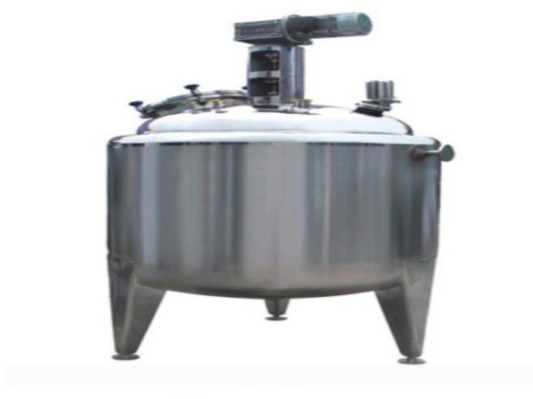
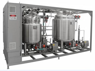
The enzymatic hydrolysis reactor, also known as an enzymatic hydrolysis tank, enzymatic reaction tank, or enzymatic reactor, is a stainless-steel vessel. We design it to provide the temperature required for enzymatic hydrolysis processes. Additionally, it offers stirring and mixing functions to maintain enzyme activity, facilitate enzyme action, and accelerate and complete the biological reaction process.
2. Principle of Biological Enzymatic Hydrolysis Technology
Biological enzymatic hydrolysis technology utilizes suitable biological catalysts (i.e., biological enzymes) to decompose substances. Specifically, it accelerates the decomposition and conversion process of these substances and transforms them into utilizable materials. This transformation helps achieve the objectives of experiments or production processes. In simple terms, we use an enzymatic reactor to separate substances or accelerate biological synthesis through enzymes.
3. Core Structure of the Enzymatic Hydrolysis Reactor
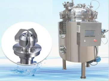
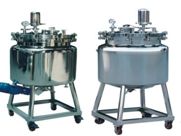
3.1 Tank Body and Stirring Mechanism
We equip the tank body with a feeding port and a discharging port to facilitate material input and output. The stirring mechanism consists of a stirring motor and a stirring impeller. We install the stirring motor at the top of the tank body, and its stirring shaft passes through the tank shell to connect and fix with the stirring impeller in the tank cavity. Moreover, we set a discharging control valve on the discharging port of the tank body to regulate the discharging process.
3.2 Discharging System
Below the outlet of the discharging control valve, we install a discharging pipe that is perpendicular to the channel of the discharging control valve. We connect and fix the channel of this discharging pipe with the channel of the discharging control valve to ensure smooth material flow. Furthermore, we install a screw rod inside the discharging pipe, and we fixedly connect this screw rod to the rotating shaft of a motor. We mount the motor at one end of the discharging pipe to drive the screw rod and promote discharging.