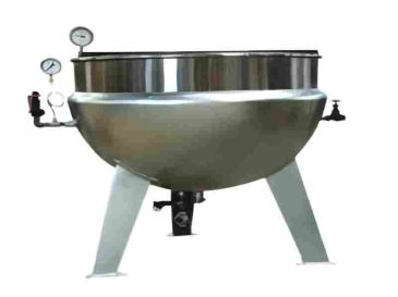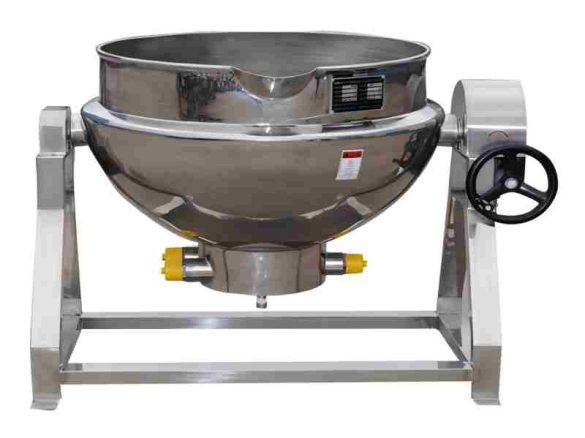
All parts of the electrically heated jacketed kettle that come into contact with food are made of 06Cr19Ni10 stainless steel, which complies with the requirements of the Food Hygiene Law of the People’s Republic of China. It features an attractive appearance, rational design, compact structure, convenient installation, simple operation, flexible use, safety and reliability, as well as easy maintenance. Thus, it is widely favored and praised by users.
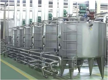
It is widely used in food processing industries such as candy, pastry, beverage, fruit juice, jam, preserved fruit, dairy products and canned food, as well as brewing, winemaking, pharmaceutical and daily chemical industries. It serves purposes like material melting, disinfection, heating, blanching, precooking, preparation, boiling, steaming and concentration. Meanwhile, it is also suitable for large hotels, restaurants, inns, dining halls, industrial and mining enterprises, government agencies, military units, and university canteens, for uses such as cooking porridge, simmering soup, boiling dumplings, stir-frying dishes and stewing meat.
It is widely used in food processing industries such as candy, pastry, beverage, fruit juice, jam, preserved fruit, dairy products and canned food, as well as brewing, winemaking, pharmaceutical and daily chemical industries. It serves purposes like material melting, disinfection, heating, blanching, precooking, preparation, boiling, steaming and concentration. Meanwhile, it is also suitable for large hotels, restaurants, inns, dining halls, industrial and mining enterprises, government agencies, military units, and university canteens, for uses such as cooking porridge, simmering soup, boiling dumplings, stir-frying dishes and stewing meat.
| Model | Volume (L) | Heat Transfer Area (㎡) | Inner Diameter (mm) | Depth (mm) | Maximum Width (mm) | Height (mm) | Weight (kg) |
|---|---|---|---|---|---|---|---|
| 50L | 50 | 0.39 | 550 | 400 | 880 | 820 | 80 |
| 100L | 100 | 0.77 | 710 | 480 | 1000 | 870 | 106 |
| 200L | 200 | 1.29 | 840 | 530 | 1050 | 915 | 121 |
| 300L | 300 | 1.34 | 930 | 600 | 1100 | 960 | 139 |
| 400L | 400 | 1.98 | 1000 | 640 | 1120 | 1050 | 193 |
| 500L | 500 | 2.30 | 1080 | 680 | 1150 | 1090 | 251 |
| 600L | 600 | 2.70 | 1200 | 790 | 1280 | 1110 | 274 |