Product

 Vacuum Blending Tank

Overview

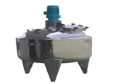
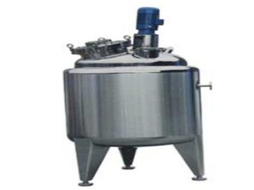
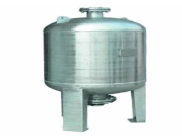
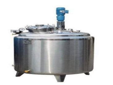
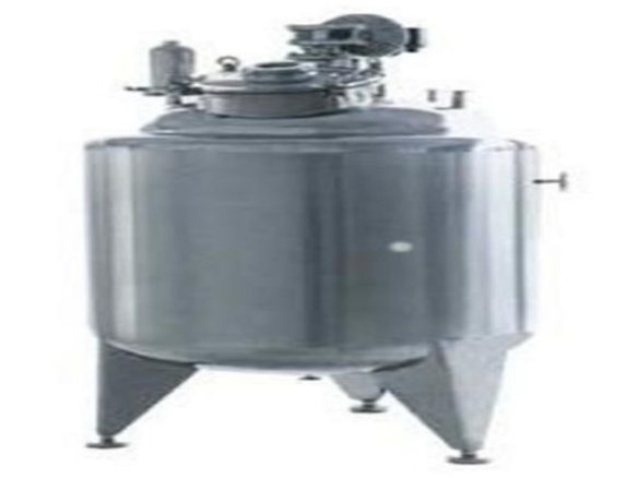
Blending tanks (also known as mixing tanks or compounding tanks) are typically vertical mixing vessels. A vacuum blending tank operates by transferring materials into the tank through gravity flow or vacuum suction. It utilizes jacket steam heating or electric heating methods to heat the materials, enabling the preparation of liquid mixtures under vacuum or normal pressure conditions. This stainless-steel vessel is designed to meet specific process requirements and is widely used in industries such as pharmaceuticals, biotechnology, food and beverage, fruit wine, condiments, fine chemicals, and oils.

Structural Components

A vacuum blending tank consists of the following key components:
  1. Tank Body (Cylinder)
  2. Tank Cover (Head)
  3. Jacket or Coil (for heating/cooling circulation)
  4. Top-mounted Mechanical Agitator (anchor-type, paddle-type, turbine-type, etc.)
  5. Transmission System (motor and gearbox)
  6. Shaft Sealing Device (mechanical seal)
  7. Supports (platform, legs)
  8. Insulation Medium
The tank can be configured to inject specific solvents or other mixing media during the blending process according to process requirements. Additional features such as a heating jacket, insulation layer, cooling system, and temperature control unit enable precise temperature regulation (heating, cooling, isothermal maintenance, and thermal insulation) required for various reaction processes. Depending on the desired automation level, the tank can be equipped with an electrical control panel of different configurations.

Structural Characteristics

. Material Heating Temperature

  • Maximum heating temperature: ≤320°C.
  • Heating methods and configurations vary based on temperature and time requirements:
    • Electric heating elements with different power ratings
    • Steam heat sources with different pressure grades
    • Thermal media with different temperature specifications
  • Temperature control system:
    • Thermocouple with insulation or PID isothermal control
    • Temperature control accuracy: ±≤1°C
  • Optional temperature display and control devices:
    • Digital temperature gauge
    • Temperature sensor with controller
    • Two-point temperature measurement method

2. Vacuum Feeding/Discharging

  • Operates under vacuum conditions for liquid mixture preparation.
  • Material transfer via vacuum suction or discharge.

3. Tank Body Construction

  • Inner tank: SUS304 or SUS316L stainless steel
  • Jacket: Q235-B carbon steel or SUS304 stainless steel
  • Outer insulation shell: SUS304 stainless steel
  • Inner surface finish: Mirror polish, Ra≤0.4μm
  • Outer surface finish: Mirror polish or 2B horizontal grain
  • Jacket types (selected by heating method):
    • Full jacket
    • Half-pipe jacket
    • Detachable jacket
  • Insulation materials: Pearl cotton, rock wool, or polyurethane foam
  • Shell surface treatment: Mirror polish, 2B matte finish, or 2B frosted matte

4. Upper Cover Design

  • Two-piece hinged removable cover (with inclined bottom or conical/elliptical/dished head) for easy cleaning
  • Alternative structures: Top-bottom conical heads or top-bottom elliptical/dished heads
  • Inner surface: Mirror polish (Ra≤0.4μm)
  • Outer surface: Mechanical polish to Ra≤0.8μm

5. Tank Bottom Structure

  • Spun-formed R-angle design welded to the inner tank
  • Polished to eliminate dead corners
  • 5° slope toward the discharge port for complete material evacuation

6. Agitation System

  • Top-mounted central (or offset) agitation
  • Detachable coupling between gearbox output shaft and agitator shaft for easy disassembly and cleaning
  • Agitation speed: 15~120r/min (fixed or customizable)
  • Agitator types (process-specific):
    • Frame type
    • Anchor type
    • Paddle type
    • Turbine type
    • Custom designs per client requirements

7. System Configurations

  • Electrical control panel (includes temperature controller, level gauge, pressure indicator, switches, indicators, spotlight controls, etc.)
  • Manhole, material inlet/outlet, heating/cooling medium ports, spare ports, cleaning ports, sterilization ports, sampling ports, temperature gauge ports, pressure gauge ports, vacuum ports

8. Nozzle Welding Technology

  • All process nozzles feature flanged arc transitions at welding points with the inner tank
  • Smooth surface eliminates dead corners for easy cleaning and aesthetic appearance

Technical Note:

  • All contact surfaces comply with GMP standards for pharmaceutical and food-grade applications.
  • Pressure and vacuum ratings are custom-engineered based on process requirements.
  • Optional automation upgrades: PLC control, SCADA integration, and remote monitoring systems.

Technical Specifications

Nominal Volume 100L 300L 500L 1000L 2000L 3000L 5000L 10000L
Inner Diameter (mm) 500 800 900 1100 1400 1500 1800 2100
Heat Transfer Area (m²) 0.9 2.0 2.7 4.5 7.5 10.0 13.5 22
Agitation Power (kW) 0.55 0.75 1.5 3.0 4.0 5.5 7.5 11.0
Rotation Speed (r/m) Fixed speed or frequency conversion
Agitation Type Custom-designed based on material properties
Working Pressure (MPa) Custom-engineered per process conditions
Working Temperature (°C) 0-200°C
Jacket Heating/Cooling Media Steam, cooling water, or other refrigerants (e.g., ethylene glycol, silicone oil)
Metering Method Weight-based liquid preparation, level measurement, or flow metering
Insulation Material Polyurethane or rock wool
Nozzle Configuration Customizable upon request (subject to process requirements)
Tank Material SUS304 / SUS316L

Leave Message