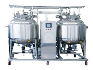
The solution tank is mainly used in dairy, chemical, food, beverage, pharmaceutical, medicine and other industries, especially in the pharmaceutical industry.
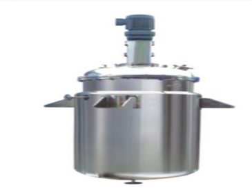
The liquid preparation tank has different names depending on its application. In pharmaceutical liquid preparation systems, it is commonly referred to as a liquid preparation tank, concentrated preparation tank, dilute preparation tank, stainless steel liquid preparation tank, sanitary-grade liquid preparation tank, injection preparation tank, and pharmaceutical sanitary-grade liquid preparation tank. In the food and dairy industry, it may be called a mixing tank, preparation tank, or sterile liquid preparation tank. Based on the volume of the liquid preparation tank, they can be classified into laboratory liquid preparation tanks, pilot-scale liquid preparation tanks, and large-scale liquid preparation tanks. Depending on whether they are mobile, they can be divided into fixed liquid preparation tanks and portable liquid preparation tanks; some are also detachable liquid preparation tanks. According to the type of stirring method, there are magnetic stirring liquid preparation tanks and agitator-type liquid preparation tanks, as well as buffer liquid preparation tanks. Based on their structure, they can be categorized into single-layer liquid preparation tanks, insulated stirring liquid preparation tanks, and three-layer insulated liquid preparation tanks.
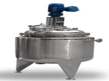
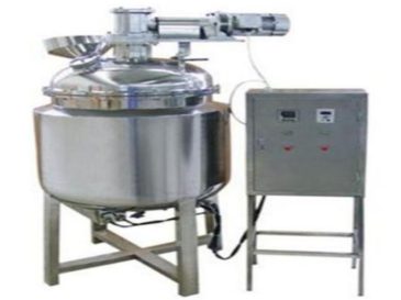
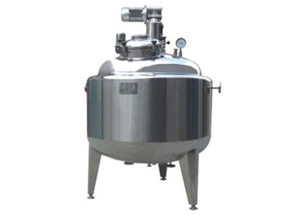
The solution tank is designed with advanced technology and fully complies with national GMP certification requirements. The tank body adopts a vertical double-layer structure, with an inner liner polished to a precision of RaO.45. The inner cylinder is wrapped with spiral heating bands and filled with polyurethane material for insulation. The exterior uses mirror or frosted glass panels for insulation, ensuring uniform luster throughout the tank. All components that come into contact with the solution are made of 316L material, while others are made of 304 material. The bottom head of the inner cylinder is concave-convex, featuring a radial flow agitator on the side wall. The top of the tank has an inlet, reflux port, sterilization port, cleaning ball, access hole for packing material, and a 0.22um air breather installed at the breathing port, along with a stirring system. The bottom of the tank is equipped with a condensate outlet, discharge port, sludge discharge port, sampling port, temperature probe, and level sensor. A control cabinet is provided for operation, with instruments displaying the solution temperature and level, offering upper and lower limit alarm functions. According to user requirements, the dilution tank can be equipped with a nitrogen charging device and a PH meter.
This structure combines upper and lower elliptical heads with a honeycomb jacket. The reducer uses a horizontal worm gear, featuring a small jacket space, forced circulation, large heating area, high efficiency, high pressure resistance, and energy-saving time compared to conventional jackets. It also has the advantage of being aesthetically pleasing. However, it has multiple welds, complex manufacturing processes, and high technical content. The horizontal worm gear reducer can be reduced in height by about 250-330mm compared to vertical reducers.
| nominal capacity | 100L | 200L | 500L | 1000L | 2000L | 3000L | 5000L |
| Inner diameter size (㎜) | 500 | 600 | 900 | 1100 | 1400 | 1500 | 1800 |
| Heat transfer area (㎡) | 0.9 | 1.5 | 2.7 | 4.5 | 7.5 | 10 | 13.5 |
| power of agitator (kw) | 0.55 | 0.75 | 1.5 | 3 | 4 | 5.5 | 7.5 |
| Speed (r/min) | Constant speed or variable frequency speed control | ||||||
| Form of mixing | Shovel blade type, anchor type, frame type, etc., the specific material properties are selected | ||||||
| Work pressure (Mpa) | Designed and manufactured according to process conditions | ||||||
| working temperature ℃ | -10°-300° | ||||||
| Heating/cooling medium for jacket | Steam, thermal oil/cold water, cold oil | ||||||