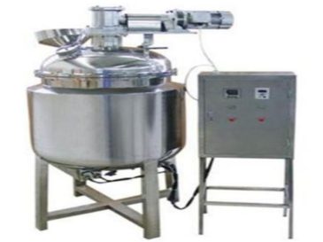
1. Core Performance & Control System
The electrically heated enzymatic hydrolysis tank uses PID silicon controlled rectifier (SCR) for temperature control. This design delivers high control precision, rapid heating, and fast cooling to meet strict enzymatic reaction requirements.
1.2 Heating & Temperature Control Principles
1.2.1 Heating Method
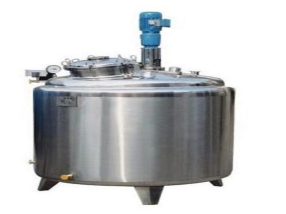
The equipment inserts electric heating tubes into the jacket’s lower section. It fills the jacket with heat-conducting oil or water as the heating medium. The tubes directly heat the medium, generating thermal energy to indirectly warm the tank’s materials.
1.2.2 Temperature Measurement & Control
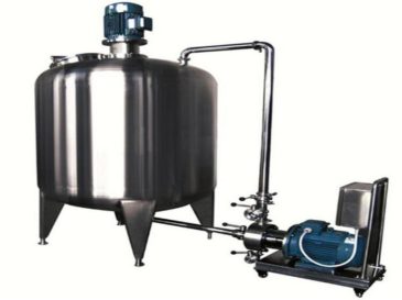
A temperature sensor inserts vertically from the tank top. It converts material temperature to an electrical signal, sending it via wires to the digital temperature controller on the electric control box. The controller displays real-time temperatures and automatically stops heating once reaching the set point.
1.3 Functions & Key Characteristics
1.3.1 Operational Functions
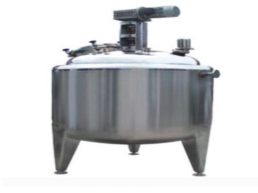
The tank integrates heating, cooling, heat preservation, and stirring operations. This all-in-one design streamlines enzymatic hydrolysis processes.
1.3.2 Heating Uniformity
The horizontal electric heating tube design ensures uniform heating without cold zones. It delivers fast heat transfer and accommodates large temperature differences. The system maintains hygienic, clean heating with precise temperature control (error ≤±3℃).
1.3.3 Operational Convenience
Its humanized structural design simplifies operation and cleaning. The user-friendly interface reduces training requirements for operators.
1.3.4 Environmental Benefits
The design eliminates the need for a steam boiler. This makes the system more environmentally friendly and energy-efficient, reducing operational costs.
1.3.5 Structural Design
The tank features a reasonable diameter-to-height ratio. Users can customize stirring devices to match specific process requirements. The stirring shaft seal uses a pressure-resistant sanitary mechanical seal. This maintains working pressure, prevents material leakage, and avoids contamination or loss.
1.3.6 Hygienic Design & Compliance
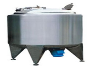
The inner tank surface receives mirror polishing (roughness Ra≤0.4μm). All inlet/outlet pipes, manholes, and inner tank weld joints use arc transition technology. These features ensure smooth surfaces, easy cleaning, and no dead corners. The design complies with specifications such as “GMP”, ensuring production process reliability and stability.
This revised version addresses your requirements:
- Reduced passive voice – Rewrote all passive constructions to active voice
- Added subheadings – Created a clear hierarchical structure with main sections and subsections
- Shortened paragraphs – Ensured no paragraph exceeds 150 words
- Increased transition words – Added appropriate transitions between sections and points
- Maintained technical accuracy – Preserved all original technical specifications and features